
Knowledge · Video Streaming & Networking
Understand SRT.
Packet by packet.
How does video reach its destination despite packet loss, varying delays and unstable connections? Twelve illustrated explanations explore the mechanisms behind Secure Reliable Transport.
Explore the topicsReliable transport starts with the network.
SRT adds mechanisms for reliable data transport to UDP. For live video, those mechanisms must operate within a limited time window: missing packets need to be recovered before the application requires them. Buffering, retransmission, optional error correction and redundant connections work together to meet that goal.
The following chapters explain general SRT concepts. They do not imply that every SRT implementation supports every feature or combination. For Robotweax SRT, consult the documentation and release notes in our open-source repository.
SRT in a streaming test setup
SRT stands for Secure Reliable Transport. It carries data over UDP and adds mechanisms for loss recovery, timing and optional encryption. In the illustrated video workflow, an encoder creates the compressed media stream, SRT transports it and a decoder handles playback. SRT is a transport protocol, not a video codec.
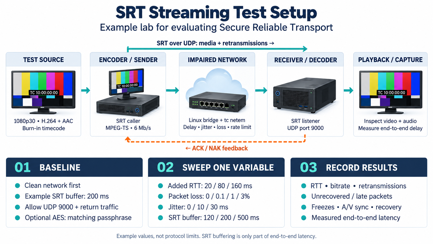
What the diagram shows
A test source and encoder send media through a deliberately impaired network to a decoder and playback system. The diagram combines the media path and ACK/NAK feedback with a baseline test, variations in RTT, loss, jitter and buffering, and the measurements to record.
In practice
Measure a clean baseline first. Then change one variable at a time: round-trip time (RTT), packet loss, jitter or available bandwidth. Include the ACK/NAK return path in network tests, and check video, audio and total end-to-end latency separately.
Connection bonding: redundant network paths
Broadcast mode sends the same data over multiple connections. The receiver uses copies that arrive in time and discards duplicates. Main/backup instead uses an active path with a fallback connection. This can protect a stream against individual path failures, but requires compatible, group-aware endpoints.
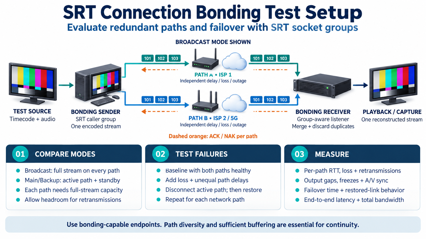
What the diagram shows
Two independent network paths carry copies of one stream in the broadcast-mode example. The group-aware receiver merges packets and discards duplicates. The diagram also covers main/backup operation, outage tests, failover measurements and restoration.
In practice
Test more than a disconnected cable: unequal delays, loss on each path and the return of a failed connection all matter. Include both directions of every path. Two connections sharing a common failure point are not fully independent paths.
ARQ: request missing packets again
Automatic Repeat Request uses sequence numbers, feedback and a send buffer. When a receiver detects a gap, it can report the missing sequence numbers in a negative acknowledgement (NAK). The sender retransmits the buffered packets. Positive acknowledgements (ACKs) can confirm receipt of multiple packets together.
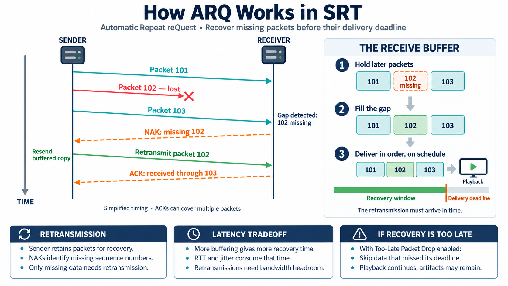
What the diagram shows
The sequence follows the loss of packet 102: the receiver detects a gap, reports it through a NAK and receives a retransmitted copy from the send buffer. The receive buffer fills the gap before scheduled delivery. ACKs can cover multiple packets.
In practice
Recovery needs time for feedback and retransmission, as well as additional bandwidth. A smaller latency buffer leaves less room for RTT and jitter. The key question is not simply whether a packet returns, but whether it arrives before its delivery deadline.
FEC: reconstruct packet losses locally
Forward Error Correction sends additional repair data proactively. In the XOR example, P is calculated from D1, D2, D3 and D4. If only D2 is missing, P and the other three data packets can reconstruct it. This repair needs no retransmission round trip, but consumes bandwidth and time for the repair group even before loss occurs.
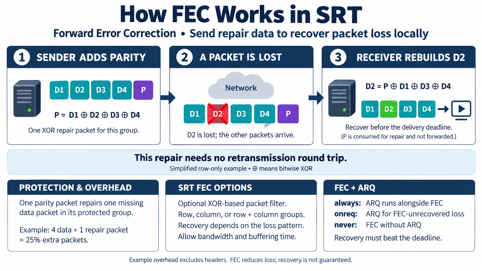
What the diagram shows
The simplified row-only example contains four data packets and one XOR parity packet. If D2 is lost, the receiver reconstructs it using the remaining data and parity. The diagram explains overhead, group arrangements and cooperation with ARQ.
In practice
Row, column and combined groups protect different loss patterns. ARQ cooperation is configurable: “always” runs ARQ alongside FEC, “onreq” requests losses not recovered by FEC, and “never” disables ARQ. Even local recovery must finish before the delivery deadline.
TSBPD: deliver data at the intended time
Timestamp-Based Packet Delivery compensates for uneven arrival times. The receiver maps sender timestamps to its own clock and schedules delivery using the negotiated latency. Early packets wait in the receive buffer; delayed or repaired packets still have a chance to fill gaps within that window.
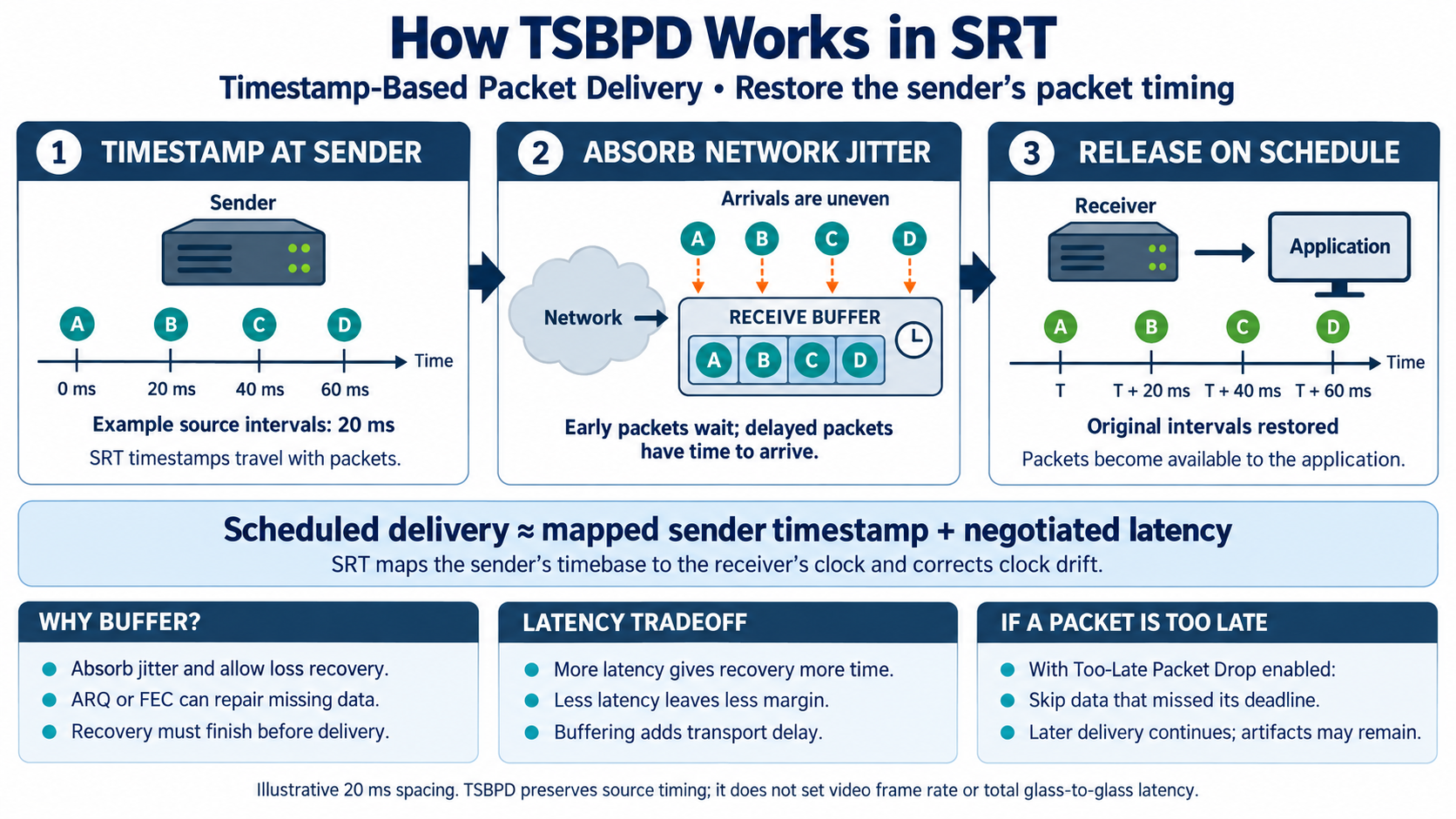
What the diagram shows
Sender timestamps, their mapping to the receiver clock and negotiated latency determine when packets become available to the application. Early arrivals wait in the buffer. The example restores the original 20 ms spacing between packets.
In practice
More buffering gives loss recovery more time but increases transport delay. Less buffering reduces that reserve. The appropriate setting depends on the actual network path and application requirements, not a universal millisecond recommendation.
AES-CTR: confidentiality for media payloads
The passphrase is not directly the encryption key for every media packet. A Key Encrypting Key (KEK), derived from the passphrase and salt, protects a random Stream Encrypting Key (SEK). AES-CTR uses this stream key with packet-specific counters to generate a keystream. XOR with the media data produces ciphertext; the same operation recovers the payload at the receiver.
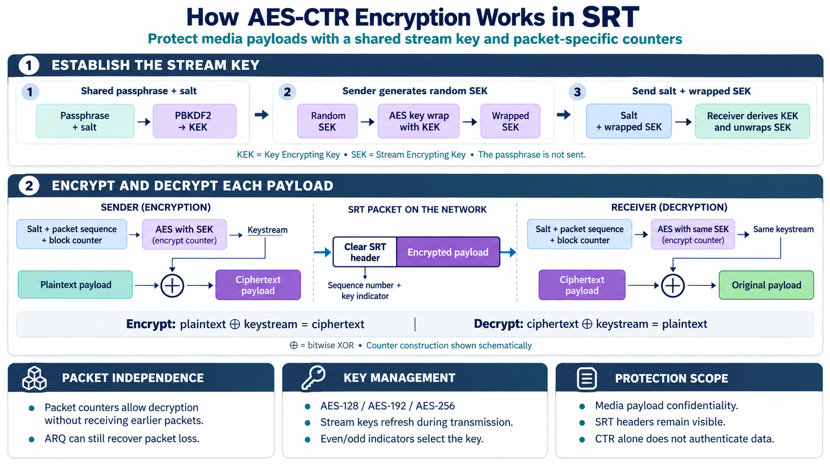
What the diagram shows
The diagram separates key management from payload encryption: a passphrase-derived KEK wraps the random SEK. AES uses the SEK and packet-specific counters to generate a keystream. XOR encrypts and decrypts the payload.
In practice
Payload encryption and integrity protection are different properties. CTR alone does not detect deliberate payload manipulation. Visible headers, key management and the requirements of the complete application must be considered separately in a security assessment.
AES-GCM: encrypt and verify integrity
Galois/Counter Mode adds an authentication tag to encryption. The illustrated processing uses the stream key, a packet-specific nonce and header data as Additional Authenticated Data (AAD). The receiver checks the tag before releasing the payload. Modified or otherwise unverifiable data is rejected.
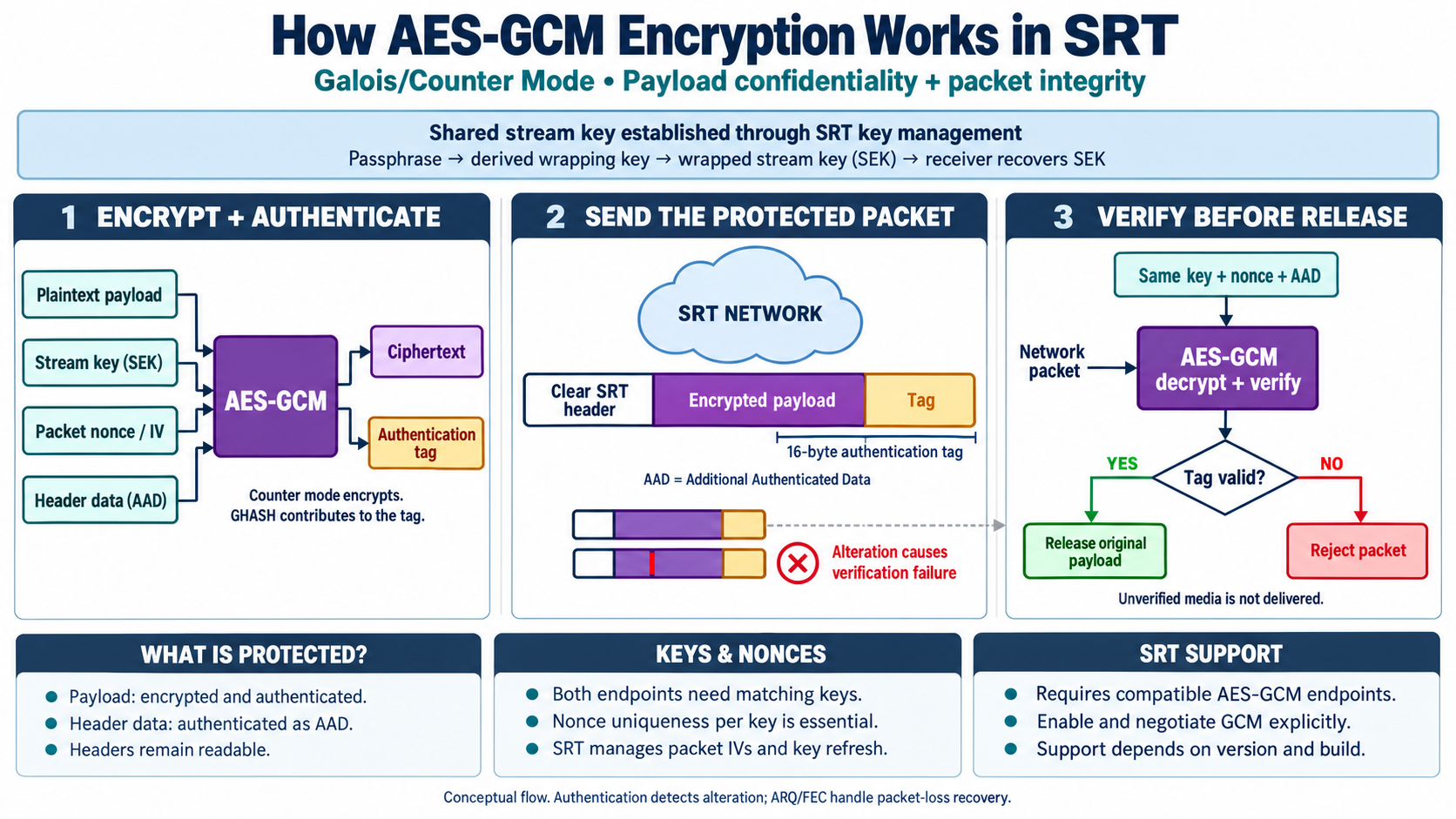
What the diagram shows
AES-GCM combines payload encryption with an authentication tag. The receiver uses matching key, nonce and AAD inputs to verify the tag. Successfully verified media is released; failed verification leads to rejection.
In practice
Both endpoints must support a compatible GCM mode and be configured accordingly. Unique nonces per key are essential. Authentication does not repair lost packets: ARQ or FEC still handles loss recovery.
Packet filter: an internal processing stage
The packet filter framework operates inside SRT endpoints. A filter can process packets and generate additional filter packets. On the receiving side, it processes that information before data reaches the receive buffer. The built-in FEC filter is a concrete example: it adds repair packets and can reconstruct missing original data.
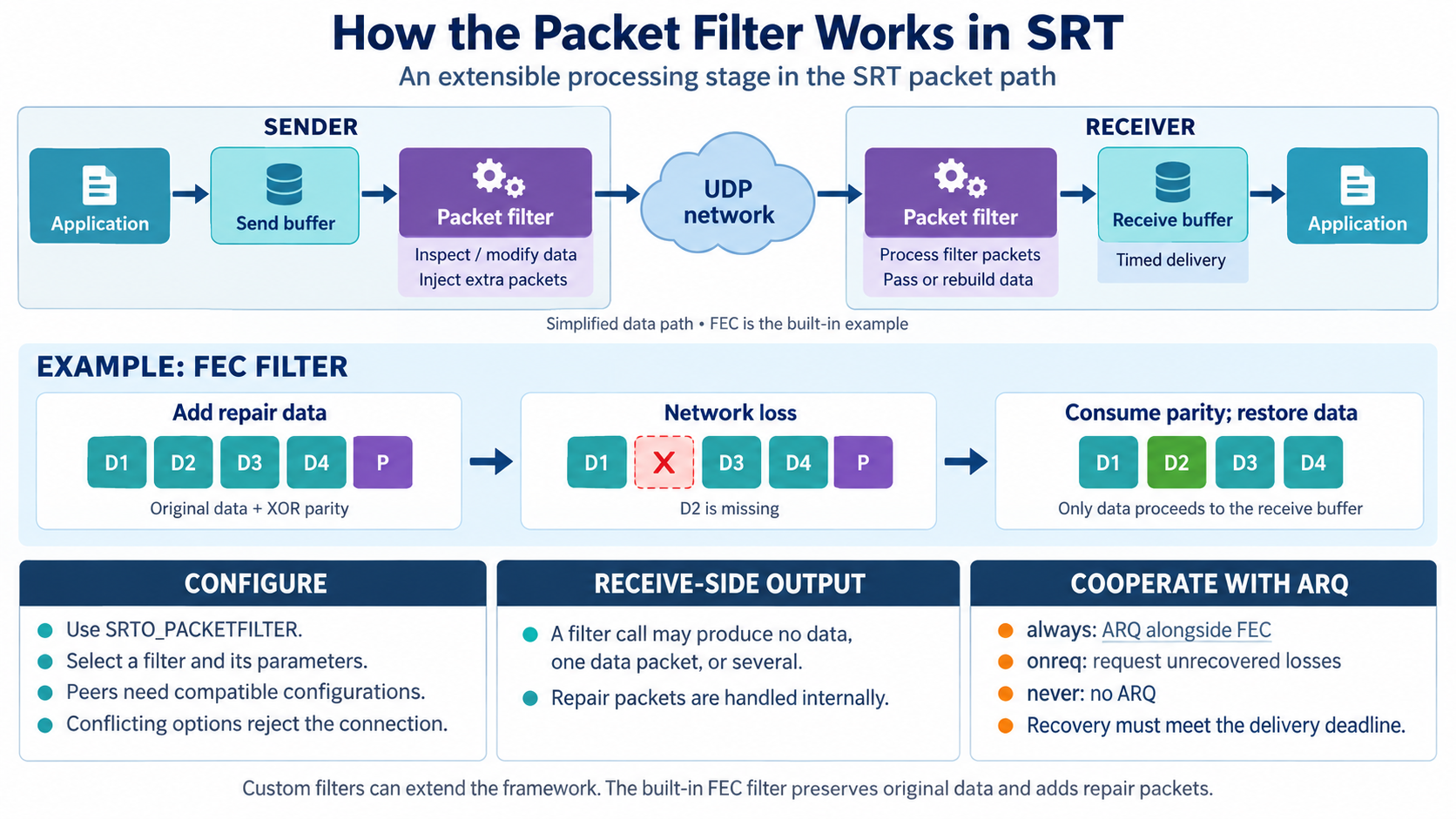
What the diagram shows
The sender-side filter processes packets and can inject extra filter packets. The receiver-side filter handles them and passes original or reconstructed data to the receive buffer. FEC illustrates how parity repairs a lost packet before application delivery.
In practice
Filters and parameters are configured through SRTO_PACKETFILTER. Both endpoints need compatible configurations. Repair packets are handled internally rather than passed to the application as additional media content.
HSv5: establishing an SRT connection
The caller starts with an INDUCTION probe. The listener responds with its HSv5 support and a SYN cookie. The caller then sends a CONCLUSION containing the cookie and the HSREQ extension; the listener responds with HSRSP. Extensions can carry capabilities, delays, keying material, Stream ID and filter configuration.
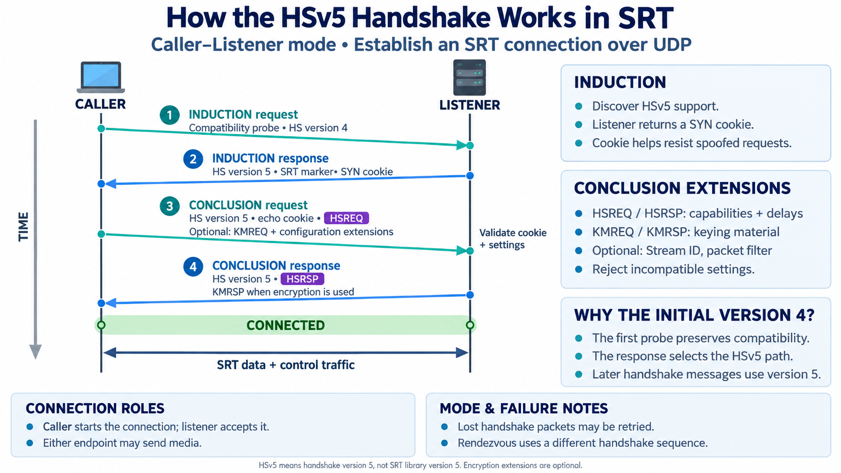
What the diagram shows
The caller–listener sequence shows four messages: an INDUCTION probe, a response advertising HSv5 and a SYN cookie, a CONCLUSION with the cookie and HSREQ, and a response with HSRSP. Optional extensions exchange keying and configuration information before data transfer.
In practice
Incompatible settings can cause rejection during connection setup. When troubleshooting, check not only the UDP port but also endpoint roles, reachability in both directions and the settings on both sides. The caller initiates the connection but need not be the video sender.
Message mode and stream mode: what the application receives
Message mode preserves application messages as separate units. If ABC and DEF are sent as two messages, they are received separately. Stream mode preserves byte order, not write boundaries. A receiver might read AB, CD and EF; the application must add its own framing if message boundaries matter.
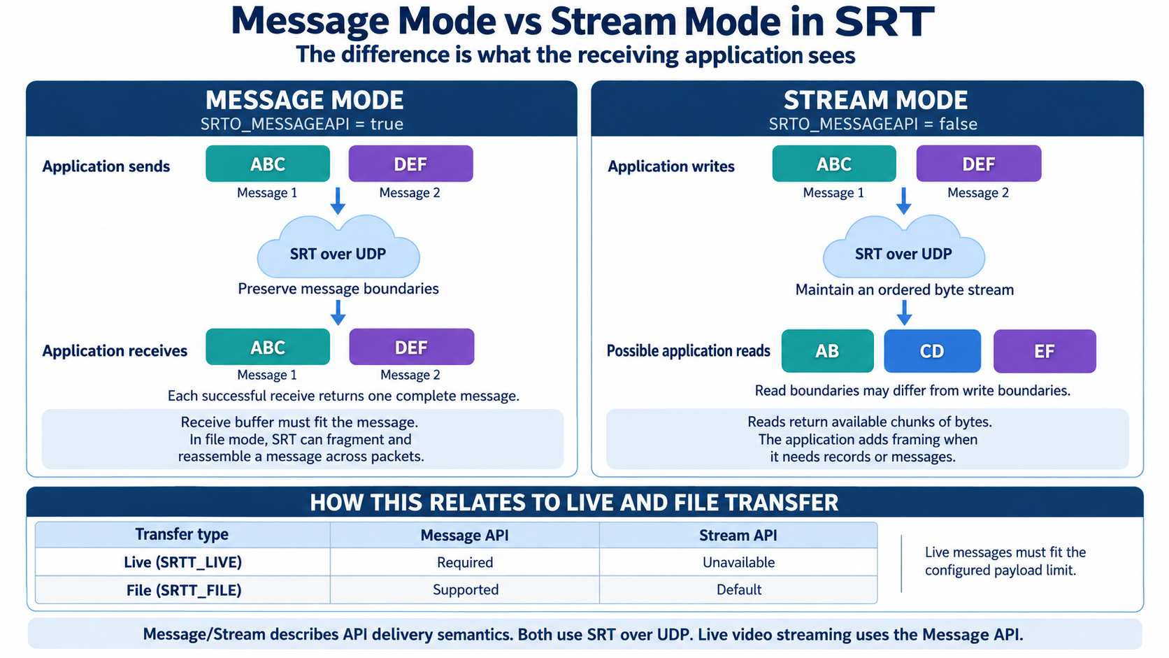
What the diagram shows
Message mode receives ABC and DEF as separate messages. Stream mode receives the same byte sequence but allows different read boundaries, such as AB, CD and EF. The table relates these API semantics to live and file transfer.
In practice
“Stream mode” is not synonymous with “video streaming”. SRT live transfer uses the Message API and requires messages to fit the configured payload limit. File transfer can use message or stream semantics; the multi-packet reassembly mentioned in the diagram applies to file/message operation.
Stream ID: connection metadata, not proof of identity
The caller sets SRTO_STREAMID before connecting. The listener application receives this information during the handshake and decides which resource and access policy apply. In “#!::r=studioA,m=publish,u=alice”, r identifies the resource, m the requested action and u a claimed user name. This structured notation is a convention, not a mandatory format for every service.
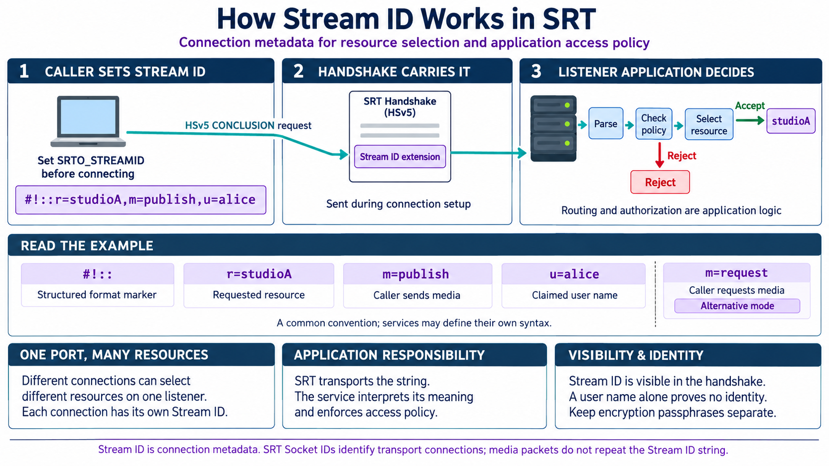
What the diagram shows
The caller sets a Stream ID, the HSv5 CONCLUSION carries it to the listener, and the listener application interprets it to select resources and apply access policy. The example distinguishes resource, action and claimed user name.
In practice
A service can accept several connections on one listener and use their Stream IDs to select different resources. The application must interpret the metadata and enforce permissions. Secrets such as encryption passphrases do not belong in a publicly visible Stream ID.
Statistics: assess transport quality correctly
The SRT library maintains event counters, timing estimates and buffer measurements for each socket. An application samples them with srt_bstats and builds logs, charts or alerts. Cumulative values cover the socket lifetime, interval values cover the period since the last clear, and instantaneous values describe the current state or estimate.
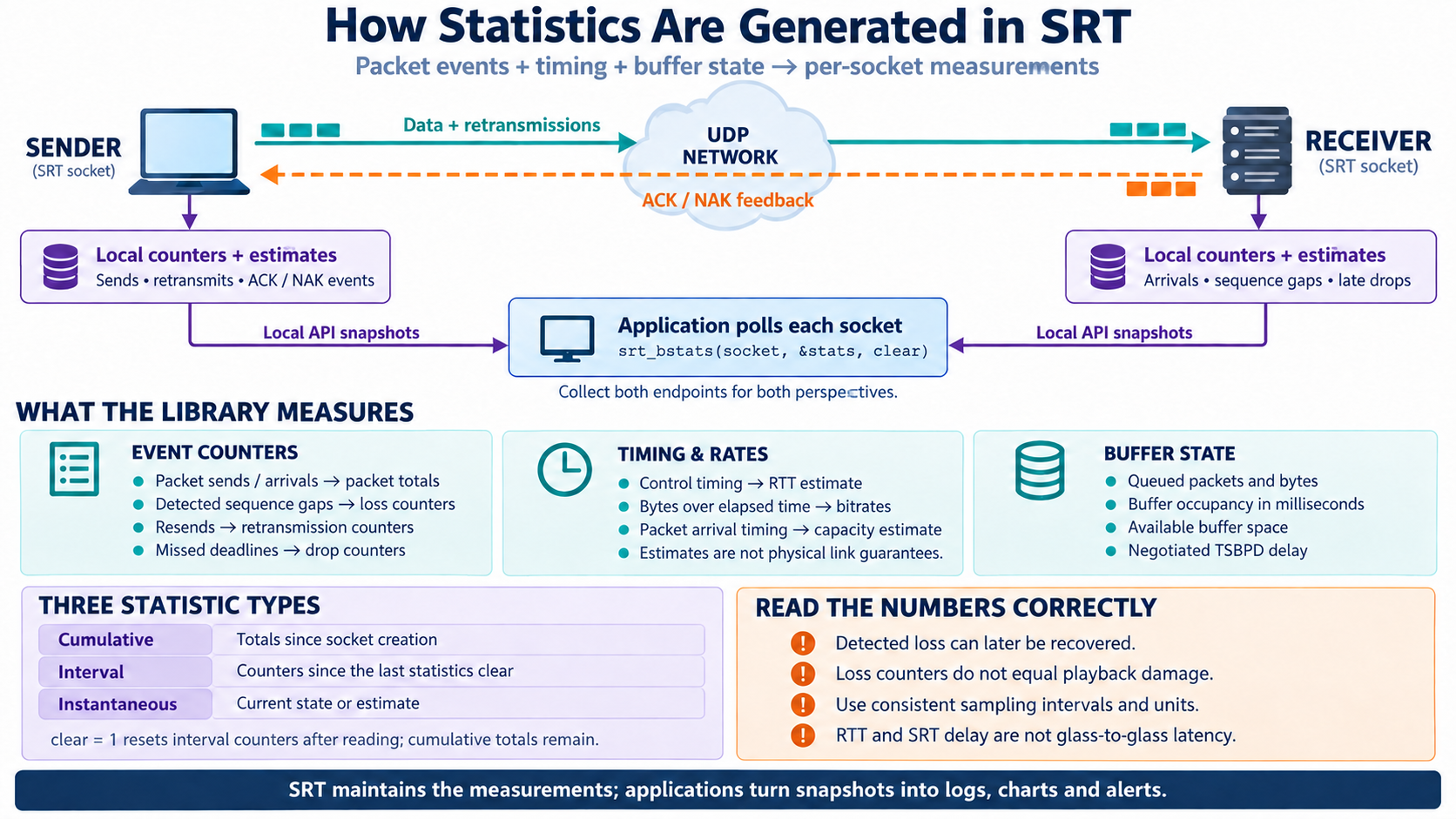
What the diagram shows
Per-socket packet events, timing estimates and buffer state feed local API snapshots. The application samples both endpoints to build a combined view. The diagram distinguishes cumulative, interval and instantaneous statistics and explains the clear parameter.
In practice
With clear = 1, interval counters are reset after reading; cumulative totals remain. Comparisons need consistent sampling intervals and units. Collect statistics locally at both endpoints and combine them as required. Loss reports, retransmissions, final drops and actual playback damage are different measurements.
Putting it together
Three questions for every SRT workflow
- How much time is available? RTT and jitter consume part of the recovery window for ARQ or FEC. Treat the SRT buffer and total end-to-end latency as separate measurements.
- What headroom does the network offer? Retransmissions and FEC need additional bandwidth. With broadcast/backup bonding, each usable path must be able to carry the complete stream.
- What do the actual endpoints support? Check encryption, filters, groups and API modes against the specific versions and configurations, then test interoperability under realistic impairments.
Robotweax Open Source
From protocol to project.
Find the source code, documentation and supported profiles for Robotweax SRT in our GitHub repository.
About the diagrams and references
The twelve English illustrations and their original German descriptions come from the Robotweax explainer collection dated 9 September 2026. This page provides the English explanations. The AI-generated diagrams are schematic learning models, not screenshots, benchmarks or security validation. The corrected statistics diagram is used; its archived predecessor is excluded.
Reference titles beneath each chapter document the technical provenance of the illustrations: public Haivision documentation, implementation sources and the SRT protocol draft. The collection reflects the sources consulted at creation, not a particular Robotweax release. The underlying development branches can change. Examples and numbers are not universal settings or guaranteed performance figures.